Glenn Ogura
The rapidly growing Internet is placing increasing demands on suppliers of passive and active fiberoptic components. No longer can these suppliers invest their research and engineering resources only into the next-generation "black box" component; they also must focus on how to manufacture these components reliably, economically, repeatedly, and at high volumes. In fact, time-to volume is becoming as important as time-to-market. Automation is a key aspect of achieving these goals but can be a serious challenge given the relative immaturity of the telecom marketplace, which requires customized solutions for the network system manufacturers and their telecom customers.
One of the fundamental manufacturing steps in building any fiberoptic component or subassembly lies in the actual stripping of the acrylate or polyimide coating off the optical fiber, exposing the glass cladding for further processing. Stripped fibers are used, for example, in hermetic sealing, pigtailing laser diodes, fiber arrays, fiber Bragg gratings, and amplifier seeding. Automation of this step is fundamental to automating many of the overall component manufacturing processes.
Conventional techniques
Optical fibers can be stripped by mechanical, chemical, or thermo-mechanical methods. Each method has its own advantages but they also have drawbacks, especially when it comes to automation, repeatability, tensile strength, quality (cleanliness) of the bare fiber surface after stripping, mid-span stripping, and applicability to stripping ribbon fibers.
Mechanical stripping uses blades to strip the fibers. It has been widely applied for end stripping of single fibers. However, the tool often must be adjusted to accommodate different fiber diameters and, over time, tool wear affects the quality of the stripping with nicks on the cladding and incomplete coating removal, which results in lower fiber and splice strength. In addition, the quality may be affected by the skill of the tool operator. Manufacturing engineers often cite process repeatability as being difficult to achieve, and mechanical stripping is not easily adapted to mid-span stripping of single fibers. This technique also is not viable for mid-span stripping of ribbon fibers.
Chemical stripping uses hot sulfuric acid or other aggressive fluids to remove the fiber's acrylate coating. Typically the fiber is bent in a loop and then dipped in the liquid. Since the minimal fiber radius must be observed to ensure fiber integrity, the minimum strip length is typically 15 mm. As packages reduce in size, this will become a more important limitation. After stripping, the fiber must be washed carefully to remove all residues; otherwise there exists the possibility of chemical wicking into space between the cladding and coating that has long-term reliability consequences. A major fiberoptic cable supplier discourages this method. Chemical methods can be used for mid-span stripping of single and ribbon fibers, but suffer the obvious safety and environmental issues.
Thermo-mechanical stripping involves the use of a thermal process to soften the fiber jacket and then a blade to complete the removal. The process is applied to end stripping of single and ribbon fibers but has technical and reliability drawbacks similar to the mechanical and chemical methods. Applying heat bunches up the coating at the ends and may not provide a clean, repeatable transition from the stripped region to the unstripped portion. There also is the risk of having surrounding fiber buffer heat-damaged, introducing long-term reliability implications. It should be noted, however, that buffer materials have higher glass transition temperatures than those of the coatings and the tight-buffer materials that are used in 900-µm fibers.
A new approach
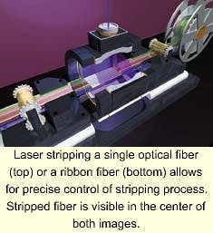
We have developed a new stripping process that uses an ultraviolet (UV) laser and a proprietary optical beam delivery and part handling system to strip the acrylate or polyimide coating from either single or ribbon fibers. The UV laser operates at wavelengths above those used for writing fiber Bragg gratings (>260 nm). This new "Reso-strip" process (patent pending) can cleanly strip a wide variety of fiberoptic cable types while maintaining high tensile strength in a statistically repeatable and reliable fashion. The quality of glass surface has been measured using optical microscopes and SEM photography.
A laser-based process offers several unique advantages over the traditional stripping methods. First, it is a non-contact process that precludes any tooling wear. Second, it is a single step, dry process that offers both environmental and throughput savings. Once the fiber is stripped, the resulting clean cladding surface is immediately ready for the next fiber preparation step, including metallization.
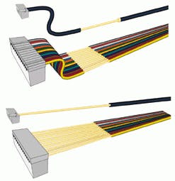
In addition, the laser beam can be directed into any portion along the fiber, making stripping programmable in terms of both length and location. This allows true mid-span stripping of both single and ribbon fibers, eliminating the need for chemicals and the associated long-term chemical wicking issues. The laser beam also can be precisely controlled, allowing complete flexibility in the strip length (as small as 1 mm), tight strip length tolerances (± 0.25 mm), and well-defined and programmable strip transition zones (0.25 ± 0.1 mm). Because of the inherent ability to direct the laser, a fiber array can be stripped with the glass carrier block or v-groove assembly attached, offering advantages in terms of final test or ease of the manufacturing material flow.
Over the past year, we have conducted both internal and external testing of various fiber cables with partners and customers. Our primary objective was to determine the repeatability and reliability of fibers stripped with the Reso-strip method. A given length of each fiber cable was stripped in the middle of the cable, then pulled at a rate of 50% per minute to obtain the tensile strength. As can be seen, this technique far exceeds the minimum tensile strength requirements. It should be noted that the laser-stripping data was conducted at approximately 50% per minute as compared to 25% per minute, the highest strain rate specified in the Telecommunication Industry Association specification, "Measuring dynamic strength and fatigue parameters of optical fibers by tension." In all tests, a sample of 30 fibers was stripped so that a statistically valid result could be obtained. All data were plotted as Weibull diagrams to show the process distribution. The slope M was calculated for each fiber type.
How it works
During the stripping process the laser beam is divided into multiple beam paths and directed by a scanning system to rotate around the fixed fiber. The beam delivery system allows the fibers to be stripped cleanly while maintaining high tensile strength. With this set up the fibers can be stripped in a reel-to-reel arrangement that incorporates integrated machine vision and fluorescence testing to automatically verify dimensional, positioning accuracy, and cleanliness. Alternatively, the laser stripping process can be configured as a stand-alone module, functioning like a pencil sharpener, into which the fiber is inserted and stripped to the desired position and length.
Sample applications
Strain relief of dense wavelength-division multiplexing hermetic fiberoptic components. The ability to perform a true mid-span strip of both single and ribbon fibers permits fiber arrays to be inserted into hermetically sealed packages while providing a strain relief "s-bend" inside the package. To fabricate such fiber arrays, the fiber is laser-stripped at a programmed location with respect to its end, then metallized with gold using customized, multi-head sputtering equipment, and finally soldered and epoxied into Kovar or stainless steel ferrules (see Fig. 1, top). This arrangement is known as hermetic ferruled fiber (HFF). In some specific cases, the fiber is only laser-stripped and metallized (Hermetic Metallized Fibers).Upon completion, the entire assembly is tested according to Telcordia GR-1209-CORE 1209, 1221, and/or 468 for hermeticity, tensile strength and optical properties, before and after a full set of endurance exposures (such as damp heat, thermal shock, and vibration) and other environmental tests to ensure 20 or more years of long-term reliability.
Alternatively, the fiber can be end-stripped for a programmed length, metallized and then attached to the hermetic package via a soldered ferrule (see Fig. 1, bottom). This method leads to undesirable exposed metallized fiber, however, creating handling problems such as cracking at the connector junction, which compound into yield and reliability issues. Even if a sleeve or loose jacket covers the metallized fiber, this requires the addition of epoxy as well as additional handing. It also complicates strain relief techniques such as "s-bending."
Fiber Bragg gratings. As fiber Bragg gratings become longer, such as those used for dispersion compensation, an automated programmable stripping process would allow for long fibers to be stripped while maintaining high tensile strength. Early studies show that stripping a hydrogen-loaded SMF28 fiber with a laser will result in a fiber Bragg grating with up to four times the tensile strength of those gratings stripped by other methods.
Hermetic fiber arrays for hostile environments. For some optical sensing applications into remote, harsh environments, hermetic fiber cables and arrays are used. For example, the optical sensing of oil wells or arterial walls have even more stringent hermeticity requirements than does the telecommunications industry.
Coupling of light. The ability to precisely strip completed fiber assemblies opens up the possibility of coupling light into the stripped fiber for such applications as amplifiers or hybrid integration of active and passive devices.
As the telecommunication industry matures, novel manufacturing methods such as laser stripping of fiberoptic cables have been devised to address the emerging applications. These include the hermetic packaging of DWDM fiber components, fiber Bragg gratings, and other specialty fibers. As the trend toward integration continues, new optical techniques and methods will be developed to address the economical scale-up of optoelectronic and MEMs-based devices.
ACKNOWLEDGMENT
The author would like to acknowledge the review comments of Osman S. Gebizlioglu of Telcordia Technologies, Morristown, NJ, for his useful insight into optical fiber stripping, and the significant technical contribution of the Optical Connectivity Development Team at Resonetics.
GLENN OGURA is vice president of marketing at at Resonetics Inc, Optical Connectivity Products Group, Nashua, NH; e-mail: [email protected]; www.resonetics.com.

