HECTOR LARA
The laser power and energy meter product lines available from leading manufacturers consist of a broad selection of modular products covering a wide range in terms of capabilities and cost. Navigating through this abundance of products can be confusing. To select the right meter for a given use, it is necessary to understand the requirements of the application and the features and limitations of the measurement technology. By clearly identifying the requirements of the application and understanding the inherent capabilities of the instruments, the selection of the appropriate product becomes a fairly methodical and straightforward process.
Detector technology
For most general-purpose power and energy meters, the detector head is sold separately from the meter, which contains the amplifier, display, and any interface electronics. This approach offers a tremendous cost advantage to the consumer. It allows the use of multiple detectors with just a single set of meter electronics, enabling economic measurements over various power, energy, pulse length, repetition rate, and wavelength domains. This modular flexibility is further enhanced in more advanced instruments, in which information on detector type and calibration data is contained on an EPROM (erasable programmable read-only memory) in the head itself, which enables "plug and play" use of detector heads and eliminates the need to input calibration information manually. This modularity also helps protect the initial investment against later changes in the application, allowing simple upgrading of the equipment.
For modular instruments, the selection process should begin with the detector head. Three basic types of detectors are commonly used—photodiodes, thermopiles, and pyroelectric detectors. Choosing the correct type and model requires understanding the operation and capabilities of each, as well as a clear identification of the laser parameters that need to be measured.
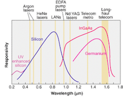
In photodiodes, incident photons are absorbed by the material and generate charge carriers (electron and holes) that can be sensed as current or voltage (see Fig. 1). Various semiconductor materials offer response over different wavelength ranges. Silicon can be optimized for performance over the 190- to 1100-nm range, germanium operates over 780 nm to 1.8 µm, and indium gallium arsenide (InGaAs) is useful between 800 nm and 1.65 µm.
Photodiodes excel at detecting low light levels because of their high sensitivity and low noise characteristics. Typical uses are direct sensing of low-power light-emitting diodes (LEDs), laser diodes and HeNe lasers, and fiberoptic measurements. When working at high powers, they are usually combined with neutral-density filters to increase the detector's dynamic range and avoid damage. Filter calibration data can be contained on an EPROM in the detector head to eliminate manual correction for the filter's spectral characteristics. Photodiodes can also deliver fast response time—even up to 40 GHz in high-speed models. Moreover, photodiodes are generally more economical than other detector types. They can also be incorporated into very compact detector heads, which is useful when performing measurements with limited physical access.
One potential disadvantage of photodiodes is that their response is not always uniform over the entire active area. This can reduce measurement repeatability when working directly with highly nonuniform beams, or when beam position on the detector varies between measurements.
A thermopile detector works by sensing radiant thermal energy in a passive absorber. This heat then flows to either an air- or water-cooled heat sink that is held at a near-constant ambient temperature. The temperature difference between the absorber and heat sink is detected by either thermocouples or semiconductor (Peltier) junctions, and this electrical signal is fed to the meter electronics.
A major advantage of thermopiles is that they deliver extremely broad spectral range, typically from about 250 nm to 11 µm. They are also capable of working over a wide range of input powers, from a few milliwatts to hundreds of watts. Because thermopiles measure total laser output, without regard to spatial distribution, they are not adversely affected by changes in beam size, position, or uniformity. Compared to other detector technologies, however, thermopiles feature relatively slow response time and are therefore best suited for measuring continuous-wave (CW) laser power, average power in pulsed lasers, or total energy from a string of pulses. They are commonly used to measure high-power argon and krypton lasers, and to perform power measurements of pulsed Nd:YAG lasers.
A pyroelectric detector also senses radiant energy, but uses a novel absorber element to directly generate the electrical signal. The absorbing element is a ferroelectric crystal that has a permanent dipole moment. Incoming light is absorbed and heats the crystal, changing its dipole moment and causing current to flow; this current is converted to a voltage and sensed by the meter. Current only flows while the dipole moment is changing, and not when it has reached a steady state condition. Thus, pyroelectric detectors cannot measure CW lasers (unless a beam chopper is used). They can only directly measure the energy of pulsed lasers, from very short pulses up to pulsewidths of 400 µs. Typical applications are energy measurements of pulsed Nd:YAG and CO2 lasers.
Thus, photodiodes produce a signal proportional to the number of photons, thermopiles respond to the power of radiation (such as watts) and pyroelectric detectors produce a signal related to the amount of radiant energy (joules).
Selecting the right detector
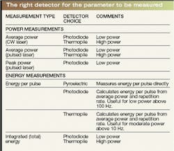
The first step in determining which of these detector types is right for a given application is to clearly identify the parameters that actually need to be measured. Examples include average power, peak pulse power, energy per pulse, or total integrated energy. While this may sound obvious, it is often a source of confusion and miscommunication between instrument users and vendors. Together, the parameter of interest and laser type determine the choice of detector (see table).
The table refers to "low" and "high" power in broad terms to provide some initial guidance. To apply this to a specific application, both total power (or energy) and maximum power (or energy) density for the laser in question should be calculated and must then be compared with manufacturer's ratings for a particular detector.
Another significant factor is beam geometry. Specifically, beam size, shape, divergence angle, and intensity distribution must be properly matched to the detector. Beam geometry can be particularly problematic when measuring the output of fiberoptics or telecommunications lasers. While photodiodes deliver the sensitivity required for optimum measurement of the low light levels involved, the highly divergent light emitted from these sources may physically overfill the active area of the detector, resulting in errors. Furthermore, inherent spatial inhomogeneity in these sources, inconsistency in detector/source positioning, and the spatial-response characteristics of photodiodes can all reduce measurement repeatability.
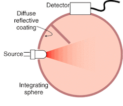
A widely accepted solution to this problem is to pair the photodiode with an integrating sphere (see Fig. 2). This is a hollow sphere in which the entire inner surface is coated with a material having very diffuse reflection characteristics. The sphere contains at least two ports—an input port to admit incoming light and an output port for the detector. The integrating sphere homogenizes the input light, regardless of its original intensity distribution, divergence, and polarization characteristics. The result is a uniform light level at the output port. This has become the standard technique in many applications, especially for telecommunications metrology.
Meter functionality and performance
The next step in the selection process is to choose an appropriate meter. The meter electronics take the raw signal from the detector and amplify, condition, and display it. For general-purpose laboratory use, the most important meter selection criteria are usually related to functionality. Some meters, for example, can perform simultaneous measurement on two independent channels and produce ratio, sum and difference outputs. This enables a signal beam to be normalized relative to a reference beam, and is useful for monitoring systems that contain a beamsplitter, such as interferometers.
Interface capabilities are another significant option for meters that operate as part of a larger data-acquisition system, or are being used in a process control setting. Typical interface options are GPIB, USB, RS-232.
For more critical applications, meter performance in terms of noise and accuracy is the primary consideration. Every power/energy meter converts input light in a proportional electrical signal, but this conversion varies slightly from head to head and meter to meter. The process of matching these characteristics to a set of previously established quantitative standards is known as calibration.
To achieve traceable calibration, manufacturers in the United States must periodically send calibration standards to the National Institute of Science and Technology (NIST), which compares the vendor's standard to their own equipment. These NIST calibrated standards are then returned to the manufacturer, which uses them as references to calibrate production systems. Traceable calibration is required for a number of applications, as well as for ISO Guide 25 and Z540 compliance and adherence to certain military specifications. Instrument buyers concerned with traceability should clearly understand the vendor's internal calibration program.
Even with traceable calibration, it is still possible for two meters to deliver slightly different values when performing the same measurement because there is always a tolerance on meter accuracy. The issue of inter-instrument correlation often becomes important in production settings when using multiple instruments to inspect a volume of products with a small margin between pass or fail.
If high correlation between multiple instruments is important, then look for products with the tightest possible specification for total system accuracy. Increasing need for improved interinstrument correlation, especially from the telecommunications market, has motivated manufacturers to improve instrument accuracy. This has been accomplished through the use of more-sophisticated electronics designs, which have lower noise characteristics, are less sensitive to drift, and possess reduced sensitivity to electrical noise generated by other equipment.
Hector Lara is senior product line manager of photonics and instrumentation at Newport Corp., 1791 Deere Ave., Irvine, CA 92606-4814; e-mail: [email protected]


