JOHN DILLON
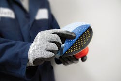
In the early days of industrial CO2 lasers, a fair amount of attention was focused on pursuing laser cutting abrasive (sandpaper) discs (FIGURE 1) as a viable market. The logic was clear, as a laser solution would eliminate the need for hard tooling. However, the economics were not favorable, as the capital cost of implementing laser technology was just too high and the production rates were too slow when compared to existing die-cutting solutions.
Additionally, those die-cutting processes were well established and there were no compelling reasons to pursue a laser solution because die cutting did not present challenges that a laser process would solve. In recent years, that has changed. This article reviews the history of producing abrasive sanding discs from well-established die-cutting practices to a laser process required to meet new demands placed on abrasive disc manufacturers.
Abrasive disc production
Abrasive material is produced in 48-in.-wide or wider master rolls, with the abrasive grit on one side of the roll substrate and a means of attachment to the backup pad on the other. The attachment methods are typically a pressure-sensitive adhesive or, more commonly, a polymer 'loop' material that will physically bond to the 'hook' surface of the backup pad (think Velcro). While the material handling systems for die cutting and laser cutting are different, they all require the ability to unroll the incoming material, process the material by performing a periphery through-cut and, if needed, produce dust-extraction holes on the disc surface, singulating the disc from the roll, removing the unused waste skeleton, and stacking the discs into counted piles for insertion into boxes for purchase by the end user.
Abrasive disc production has always been the domain of flat-bed die cutting, and for good reason. Even though lasers offered advantages, die cutting was (and in many cases remains) the most cost-effective means of production, especially for discs that only require a periphery cut or a periphery cut with large dust-extraction holes.
Flat-bed die systems use an upper platen that is attached to a hydraulic ram. The steel rule die is secured to the platen and once the hydraulic ram is actuated, the steel rule penetrates the abrasive material and the part is produced. These systems are capable of production rates up to 60 strokes/min. Additionally, if the die board is steel-ruled with three 6-in.-diameter discs, it is possible to produce 180 discs/min, resulting in high production rates for a nominal investment. A steel-rule die also has a long life and low cost because the die only costs a couple-hundred dollars and it self-sharpens while die cutting the abrasive. With this background, it is easy to see why die cutting has been the process of choice for most abrasive disc-processing applications.
Laser processing advantages
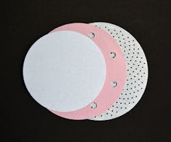
So, what is causing the shift to laser processing? A couple of reasons include the requirement for improved work environments in addition to improved debris extraction for critical finishing applications. This is especially true for the automotive body shop market. As the formulations for automotive finishes evolved, the use of dust-free holes in the abrasive disc has been a primary focus of abrasive manufacturers. The first-generation dust-free holes were fairly large in diameter, being the same size and number as the extraction holes in the backup pad, typically 6 to 8 holes that are 10mm in diameter (FIGURE 2).The 10mm slugs are removed by allowing the slugs to be captured in the punch that produces the hole, then extracted through the punch. While this strategy works well, it is not 100% effective and slugs can remain in the disc, which requires manual inspection and removal. In use, the 10mm-diameter holes offer a means of dust extraction that was not available before; however, they are far from ideal, as dust is only extracted in the area around the holes and not the entire disc surface. Additionally, alignment of the abrasive disc holes to the extraction holes in the backup pad is critical and any misalignment by the operator will have a detrimental impact on dust-extraction efficiency.
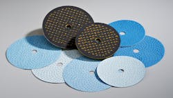
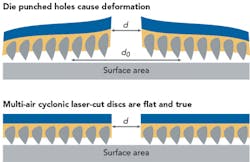
As the number of dust-extraction holes across the abrasive disc increased, not only did the dust extraction rate improve, but improved cut performance and longer disc life resulted. The drive to produce even smaller holes resulted in the only viable production option left-industrial CO2 lasers. The results have been dramatic, resulting in strong market acceptance of this product offering by abrasive manufacturers. The latest-generation discs have well in excess of 300 holes per disc, with each micro-hole being approximately 1.5mm in diameter (FIGURE 3).Producing these next-generation abrasive discs is a fairly straightforward process from a laser and motion system standpoint. High-powered, diffusion-cooled CO2 lasers integrated with large-area galvanometer motion systems provide an ideal platform for processing the discs. The abrasive rolls are typically produced in a wide web, so it is typical to have multiple laser/motion sources across the roll to increase productivity. An additional advantage with laser technology is its ability to process the abrasive discs with the web in continuous motion instead of the less-productive indexing motion of flat-bed presses. The challenges with the laser process are with the web handling equipment and developing a stable process to produce 100% slug-free holes, registering the disc periphery to the holes and handling the discreet discs once they are cut from the web of abrasive.
Producing 100% slug-free holes is critical because any 'hanging chad' left on the top or bottom disc surface has the potential to damage the surface being prepared for painting, resulting in excessive reworking of the area. With proper management of the slug removal process, it is possible to attain this demanding requirement. The dust-extraction holes are produced first in a cutting zone specifically designed to keep the raw, abrasive stock flat during processing, but still allowing for efficient slug removal in the zone. Registration of the abrasive web is maintained as the material transitions into the periphery cutting zone, where the laser through-cuts the disc periphery and separates it from the abrasive web. As the now-completed disc is separated from the web, it can drop onto a conveyor for removal from the cutting zone. The singulated discs can then be offloaded from the conveyor manually and boxed; however, this is a labor-intensive process that can be easily automated with robots. A single high-speed robot and vision system can rapidly identify the disc on the conveyor for picking and placing onto a counted stack of discs. The only manual process required is to box the counted discs and they are ready for distribution.
Conclusion
Lasers have often been referred to as a solution waiting for an application. In the case of using lasers to produce advanced abrasive discs, this was certainly the case. For many years, lasers were a possible production solution—just not an economically viable one. However, as the demands for product performance advance, many times the solution can be found in the unique advantages that a laser process can offer. In this case, a laser now provides a solution that results in greatly improved performance while improving the health and safety of the work environment. This application follows the path of many industrial laser applications, where demands for increased product performance can only be found with a laser solution. Growth in the laser market is being driven not only in the metals market but also in the paper- and polymer-converting market, where lasers offer a cost-effective solution for next-generation, high-performance products entering the market.
ACKNOWLEDGEMENT
Velcro is a registered trademark of Velcro Industries B.V.
JOHN DILLON ([email protected]) is VP of marketing/key accounts at Preco, Inc., Somerset, WI; www.precoinc.com.


