PHILIP K. PRESTON
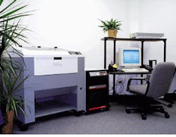
Lasers are used in many factory production environments that require external laser cooling to maintain consistent performance and minimize downtime. Some lasers can be fan cooled, but in most cases a refrigerated, recirculating chiller is used to remove excess heat and maintain the internal components of the laser at a suitable temperature (see photo). Chillers work by circulating a fluid medium (usually water or water/glycol) and cooling it using forced ambient-air heat exchange or mechanical refrigeration. The coolant is pumped through the laser heat exchanger and monitored by the chiller’s temperature controller, which responds to variations in the temperature of the returned coolant stream.
Tap-water cooling of the laser may appear to be an obvious and economical method of cooling the laser, but it is not. Even if one assumes that water is a readily available resource, it is economically and environmentally expensive to constantly pump tap water through a laser and down the drain. From a purely economic perspective, the cost of a chiller is easily justified when compared to the cumulative cost of water and sewerage bills. In addition, seasonal temperature variations affect tap water, resulting in inconsistent cooling of the laser.
Optimizing performance
A typical chiller cooling mechanism is composed of three major components—a temperature controller, coolant pump, and heat-exchange system. If these three items are not matched correctly to the specifications of the laser system, the laser may not receive the amount of cooling required to produce optimal beam generation.
In matching a temperature controller to a laser system, one can usually work from manufacturer specifications, such as 20C ۫C, for a particular laser. Available temperature-control technologies, in order of increasing sophistication as well as system performance and precision temperature control, include a bimetallic on/off thermostat, analog controller, and microprocessor proportional-integral-derivative (PID) controller.
The second major component is the coolant pump, and recirculating chillers are available with several pumping configurations. One of these, a centrifugal pump, provides excellent flow characteristics at low pressures. This pump is ideal for lasers that need a moderate flow rate and do not require high-pressure coolant flow. Another configuration, the positive displacement pump, produces consistent (usually low) flow rates at higher pressures than centrifugal pumps. Some laser manufacturers install pressure-sensing devices that must be activated by the chiller to make the laser operational. High pressure is needed to activate these sensors. A third configuration, the turbine pump, should be selected for lasers that require the coolant stream to be delivered at high flow rates and at high pressures.
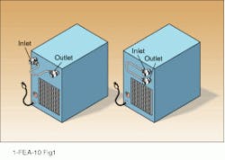
As mentioned, some lasers require a minimum coolant pressure (or flow) to be activated. If the pressure is insufficient to activate the sensor, the flow should be bypassed through an external loop installed between the chiller and laser (see Fig. 1). This loop will ensure that there is always flow through the chiller’s heat exchanger and that a "freeze-up" does not occur. A freeze-up in the heat-exchange system may be catastrophic to the life of the chiller because of the greatly increased potential for coolant to escape into the hermetic refrigeration loop.The third major chiller component is the heat-exchange system. The heat-removal capacity of a chiller is governed by the dimensions of its heat-exchange system. This is the most critical component of chiller construction and should be reviewed carefully before selecting a chiller to fulfill a laser’s cooling specifications.
Controlling the flow
One simple technique for removing heat from the coolant is a coolant-to-air heat exchanger, similar to an automobile radiator, in which forced ambient air removes heat from the coolant. No mechanical refrigeration is involved. Although this system can be the most economical choice, the degree of precision with which temperature can be controlled is limited because ambient air governs the coolant stream temperature.
A more precise heat-removal method relies on mechanical refrigeration with a refrigerant-to-coolant heat exchanger configuration. In this case, a coolant mixture of either ethylene or propylene glycol and water is recommended because of the resultant temperature range that extends below the freezing point of water. The coolant selection is a critical element of the heat-exchange process. The laser manufacturer’s heat removal capacity specification (in BTUs per hour or watts) provides a guide to selecting the appropriate one.
To achieve different temperature ranges, as well as different levels of accuracy, and stability at the output coolant stream, manufacturers of refrigerated recirculating chillers regulate the flow of refrigerant to the heat exchanger using one of three methods—a capillary-tube method, a hot-gas-bypass method, or a microprocessor-controlled method.
The refrigerant gas in the most basic small refrigeration systems is metered by a capillary tube that causes a constant refrigerant pressure drop at the point of evaporation (see Fig. 2). The capillary-tube length and diameter are calculated to achieve the optimum performance (maximum heat-removal capacity) at a specific temperature. To control coolant temperature, a heater is usually included to counteract the cooling capacity and produce a constant output temperature. The simultaneous operation of heating and refrigeration in this system limits energy efficiency.Refrigeration condenser cooling
Regardless of which refrigeration design is used, all chillers require cooling of their internal condensers. There are two primary styles of chiller refrigeration condensers—air-cooled and water-cooled. Air cooling, which cools the condenser coils by blowing ambient air over them and discharging the heated air into the environment, is most common. The water-cooling alternative requires tap water or factory-process water to cool the condenser coils of the laser chiller. Water-cooled condensers are normally selected for chillers with high heat-removal capacity installed in environments that cannot tolerate the heated discharged air that results from the air-cooled condensers.
Most laser manufacturers require that accessory chillers with specific refrigeration and pumping requirements be installed to achieve maximum operating performance. As a precautionary measure, manufacturers can install pressure, flow, and/or temperature sensors that will not allow operation if any of these criteria are not met.
Refrigerated recirculating chillers can cool a single laser, or if the heat-removal capacity is sufficient, multiple lasers. For example, a group of lasers can be cooled by installing a parallel configuration of chillers (adding cooling capacities) at a central location. From that location a shop can be "hard piped" and insulated to provide temperature-controlled coolant to several laser locations throughout the shop floor.
Philip K. Preston is the president of PolyScience, 6000 West Touhy Ave., Niles, IL 60714; [email protected].


